
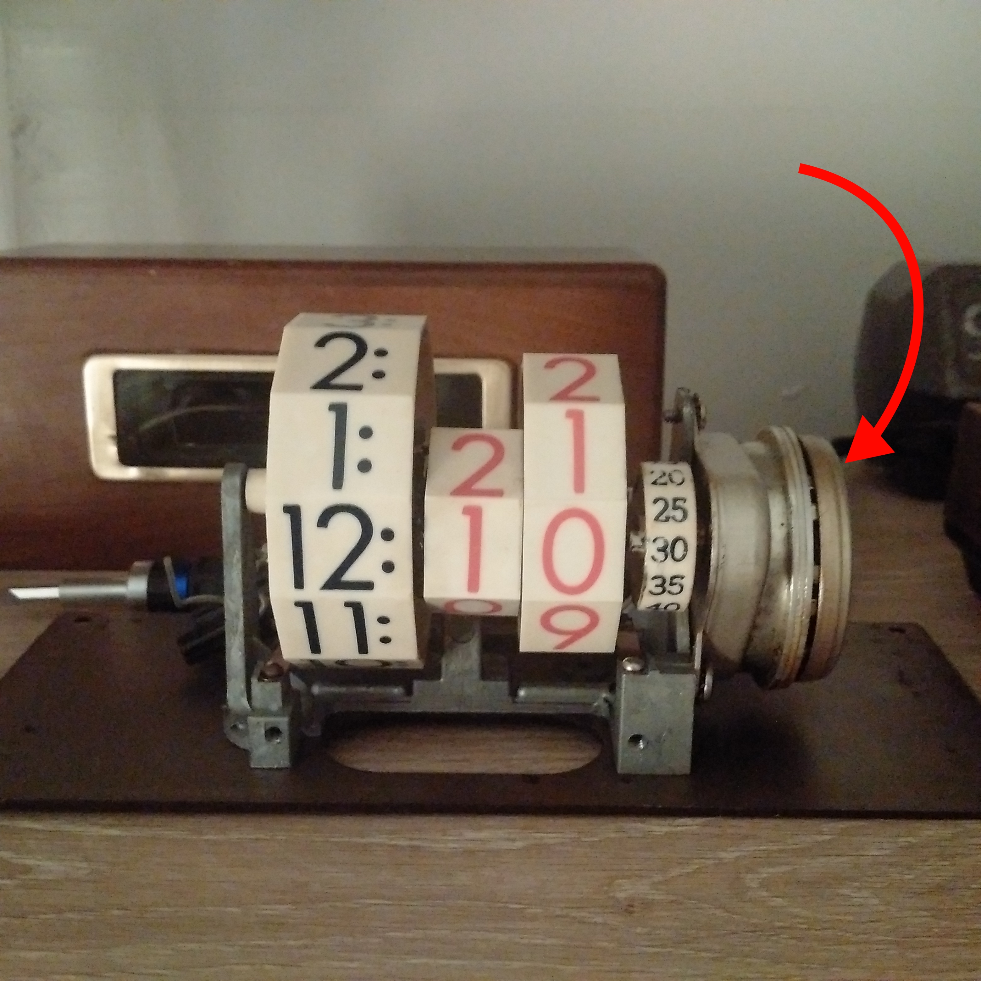
When plugged in, it still hummed, giving me hope that it was still repairable. After opening, it looks like this magnetic flywheel has become deformed, getting stuck to the alternating poles of the synchronous motor. If we can replace the flywheel, and the motor has enough power to give it high enough RPM for the main spindle to reach 1 RPM, it'll be good as new!
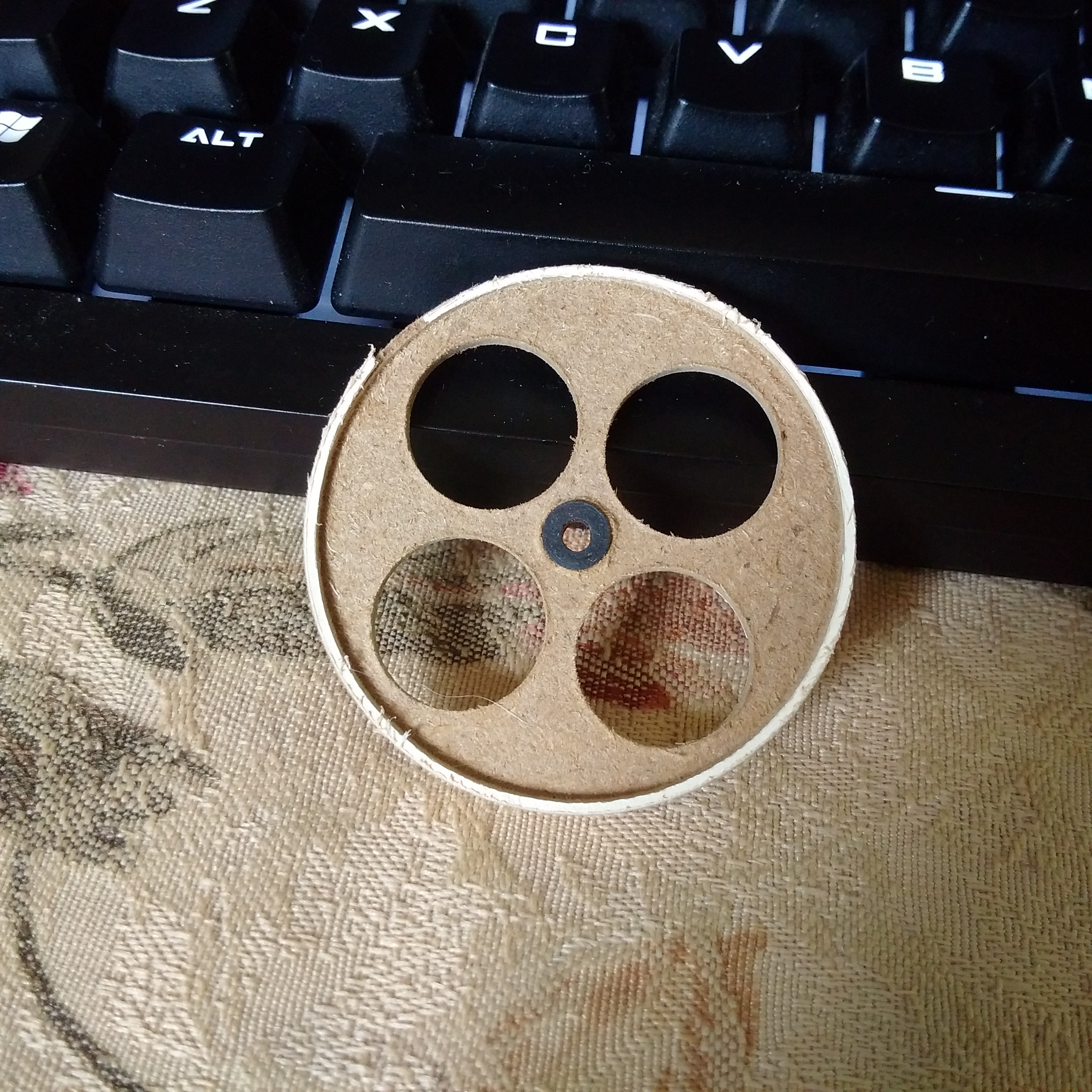
After many, many failed prototypes, this one worked long enough for me to test my hypothesis. This was made by first cutting holes to reduce weight, then using Forstner bits to cut down the center of the wheel, and using a hole saw to cut the outer portion. This resulted in a wheel with a cap-like shape, necessary for mounting the ferrous strip in proximity to the poles of the motor. Too small, and the rim will stick to the motor, too far and the metal strip will not interact with the magnetic field from the motor. In addition, mounting the flywheel has become a puzzle in itself. Pictured is a rubber seal, but I ended up friction fitting a dowel for the final design.
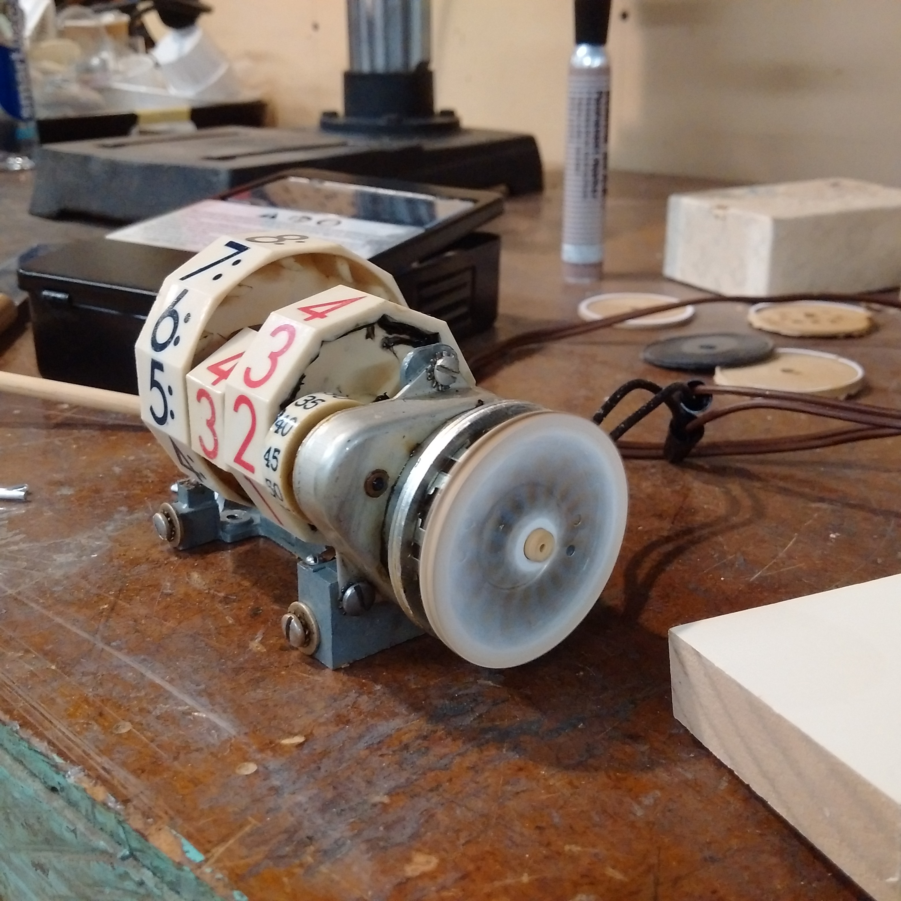
It works! Albeit, a bit slow. Removing or using a different material should help this. The prototype was built with some type of MDF.
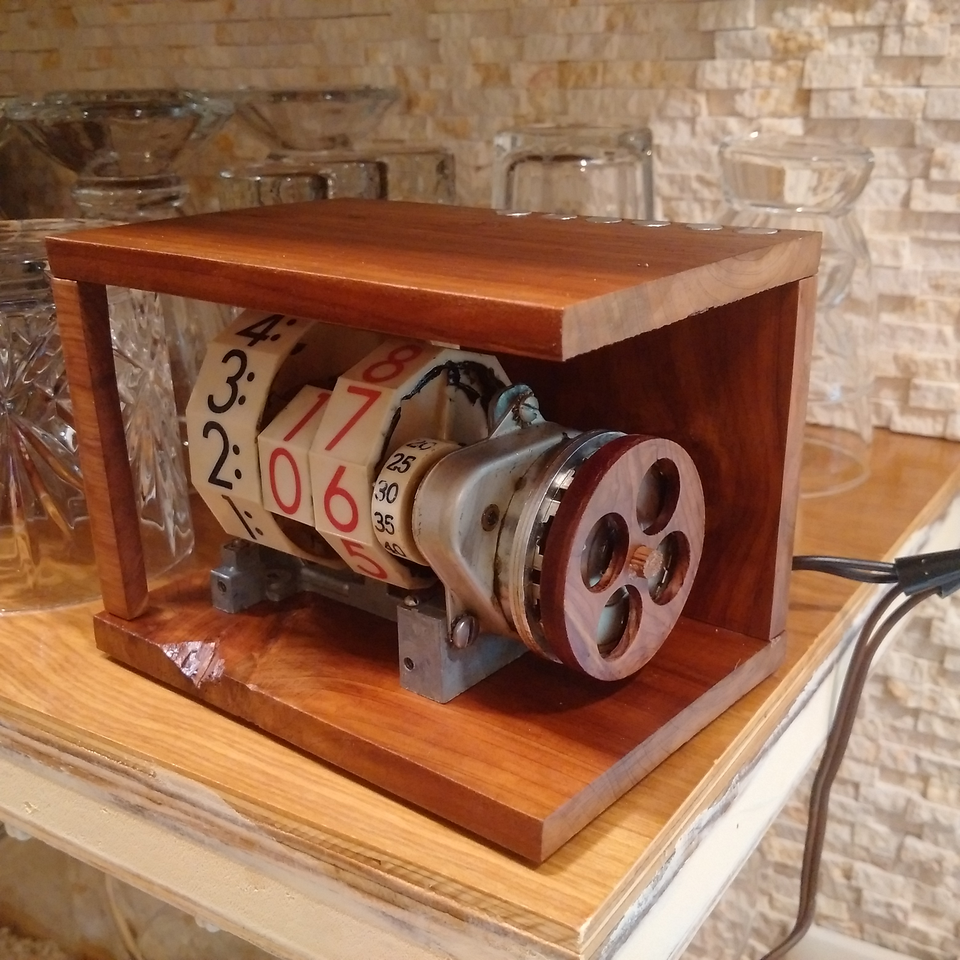
I didn't really like the original case, even though it was in fairly good condition. I decided to build the rest of the case out of cedar, since that was what I ended up building the flywheel from (a very light wood). I thought the mix of metal and wood created an interesting aesthetic.
As promised, a video of the clock in action. The idea of an analog digital clock is certainly interesting, and this was one of the first to try and utilize that design. This clock was built in the early 1960s.